Device Solves: Difference between revisions
| Line 17: | Line 17: | ||
[[File:Dev_eqn.png|200px]] | [[File:Dev_eqn.png|200px]] | ||
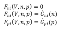
The dot term represents the time derivative component of the electron and hole electron continuity equations. | |||
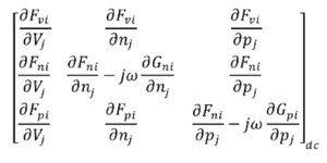
Sinusoidal Steady State Analysis (S3A) solves the device equation system in the frequency domain as a steady state perturbed by an infinitesimal signal. The small signal assumption allows linearization of the device around the DC bias point. The corresponding Jacobian takes the symbolic form: | |||
[[File:matrix.png|300px]] | |||
which is a 3Nx3N matrix (for 3 solution variables and N nodes). Notice the imaginary components in the electron and hole rows corresponding to the dot term in the continuity equation. | |||
The matrix equation now takes a form slightly different to the steady state form JX=B. | |||
[[File:matrix_eqn.png|100px]] | |||
where J remains the steady-state Jacobian at the desired DC-bias point, D is now a diagonal matrix with zeros for Poisson rows and ω=2πf for diagonal elements of its continuity rows. Both are 3Nx3N matrices. X is solution vector and B is boundary condition vector. | |||
For computational reasons(i.e. seperating real and imaginary terms), the matrix system takes the following 6Nx6N form | |||
[[File:final_matrix_eqn.png|100px]] | |||
where XR and XI are real and imaginary components of the solution variables. | |||
Revision as of 18:07, 5 January 2016
FLOODS Specific Commands
- Initial Guess - start the numerical solve off well
- contact - define contacts physically, and define contact physics
- device - bias contacts and solve steady-state or transient
Steady-State
Transient
Frequency domain
Sinusoidal Steady State Analysis
Consider the symbolic representation of the 3 device equations: Poisson, electron and hole continuity equations.
The dot term represents the time derivative component of the electron and hole electron continuity equations. Sinusoidal Steady State Analysis (S3A) solves the device equation system in the frequency domain as a steady state perturbed by an infinitesimal signal. The small signal assumption allows linearization of the device around the DC bias point. The corresponding Jacobian takes the symbolic form:
which is a 3Nx3N matrix (for 3 solution variables and N nodes). Notice the imaginary components in the electron and hole rows corresponding to the dot term in the continuity equation. The matrix equation now takes a form slightly different to the steady state form JX=B.
where J remains the steady-state Jacobian at the desired DC-bias point, D is now a diagonal matrix with zeros for Poisson rows and ω=2πf for diagonal elements of its continuity rows. Both are 3Nx3N matrices. X is solution vector and B is boundary condition vector. For computational reasons(i.e. seperating real and imaginary terms), the matrix system takes the following 6Nx6N form
where XR and XI are real and imaginary components of the solution variables.

