High Level Example: p/n Diode: Difference between revisions
No edit summary |
No edit summary |
||
| Line 13: | Line 13: | ||
[[Image:pn.jpg]] | [[Image:pn.jpg]] | ||
In order to later set meaningful boundary and initial conditions, | In order to later set meaningful boundary and initial conditions, the solution variable of electrostatic potential (DevPsi) must be defined in reference to some level. In this case, only one material (silicon) is used in the simulation and thus it is convenient to set the reference potential, or zero, to be the constant Fermi level of the silicon <math>E_f=-q\Psi_{ref}</math> and DevPsi to be the band-bending at the intrinsic Fermi level <math>E_i=-q\Psi</math> of the semiconductor as shown in the figure above. | ||
(In other devices that have multiple materials such as a mosfet or heterostructure, it is convenient to set DevPsi to be the band-bending at the vacuum level with reference to the Fermi level.) | |||
| Line 31: | Line 31: | ||
If the Quasi-Fermi approach is used, then the solution variables will be <math>\Psi</math>, <math>\Phi_{fn}</math>, and <math>\Phi{fp}</math> or "DevPsi", "Qfn", and "Qfp" implemented in FLOODS as follows. In this case, elec and hole need to be defined as | If the Quasi-Fermi approach is used, then the solution variables will be <math>\Psi</math>, <math>\Phi_{fn}</math>, and <math>\Phi{fp}</math> or "DevPsi", "Qfn", and "Qfp" implemented in FLOODS as follows. In this case, elec and hole need to be defined as constant solution variables. | ||
solution add name=DevPsi solve negative damp | solution add name=DevPsi solve negative damp | ||
| Line 38: | Line 38: | ||
solution add name=Qfp solve negative damp | solution add name=Qfp solve negative damp | ||
solution add name=Qfn solve negative damp | solution add name=Qfn solve negative damp | ||
Revision as of 15:02, 5 October 2010
This section provides an overview of all the necessary parts for simulating a p/n diode (in one material) in FLOODS.
Set up governing differential equations in the material:
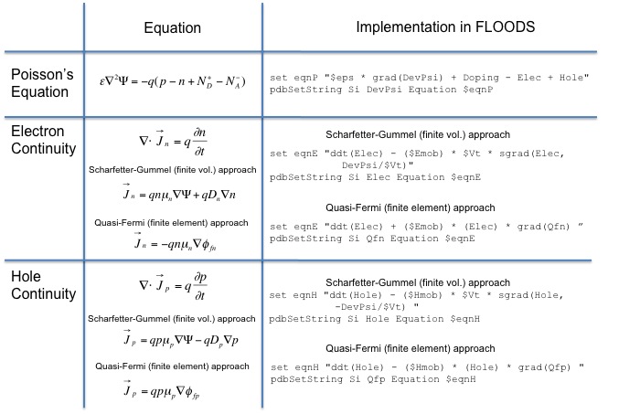
For semiconductors, the basic equations that describe transport of electrons and holes and electrostatic potential are the continuity equations for electrons and holes and the Poisson Equation as given in the table below. Other differential equations such as the heat equation could also be included in the model. The tcl/alagator scripts for the corresponding differential equations are given in the table, where"eso" is <math>\epsilon_0\epsilon_r/q</math>, "Emob" and "Hmob" are the electron and hole mobilities, and "Vt" is <math>kT/q</math>. One of two approaches may be used to implement the continuity equations (Scharfetter-Gummel or Quasi-Fermi), which use either finite volume or finite element methods, respectively.
Determine placement of the reference potential and DevPsi
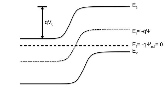
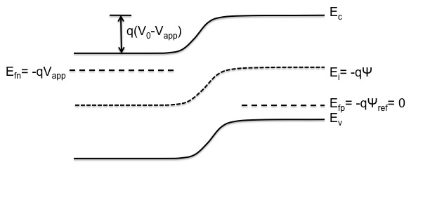
In order to later set meaningful boundary and initial conditions, the solution variable of electrostatic potential (DevPsi) must be defined in reference to some level. In this case, only one material (silicon) is used in the simulation and thus it is convenient to set the reference potential, or zero, to be the constant Fermi level of the silicon <math>E_f=-q\Psi_{ref}</math> and DevPsi to be the band-bending at the intrinsic Fermi level <math>E_i=-q\Psi</math> of the semiconductor as shown in the figure above. (In other devices that have multiple materials such as a mosfet or heterostructure, it is convenient to set DevPsi to be the band-bending at the vacuum level with reference to the Fermi level.)
Designate solution variables:
If the Sharfetter-Gummel approach is used then the solution variables will be <math>\Psi</math>, n, and p or "DevPsi", "elec", and "hole". They are implemented in FLOODS as follows.
solution add name=DevPsi solve negative damp
solution add name=Elec solve !negative
solution add name=Hole solve !negative
It is useful to define the Quasi Fermi potentials for later use in contact boundary conditions or plotting.
term name=Qfp add silicon eqn = "DevPsi + $Vt*log(Hole/$ni)"
term name=Qfn add silicon eqn = "DevPsi - $Vt*log(Elec/$ni)"
If the Quasi-Fermi approach is used, then the solution variables will be <math>\Psi</math>, <math>\Phi_{fn}</math>, and <math>\Phi{fp}</math> or "DevPsi", "Qfn", and "Qfp" implemented in FLOODS as follows. In this case, elec and hole need to be defined as constant solution variables.
solution add name=DevPsi solve negative damp
solution add name=Elec const solve val= "$ni*exp((DevPsi-Qfn)/$Vt)+1.0"
solution add name=Hole const solve val= "$ni*exp((Qfp-DevPsi)/$Vt)+1.0"
solution add name=Qfp solve negative damp
solution add name=Qfn solve negative damp
Give Boundary Conditions:
Give Initial Conditions:


